|
|
Piping System Designer
The Piping System Designer represents a giant leap in simplification of the loopfield piping tie-in design. Previously, users needed to build their own piping groups and sizing reductions to create a balanced system. With the new Piping Designer, the project specifics are directly pulled into the design and the pipe size reductions for the reverse return systems and run-outs are automatically optimized for purging and operation. Additionally, the system efficiency is evaluated and the designer is given a pipe bill of materials.
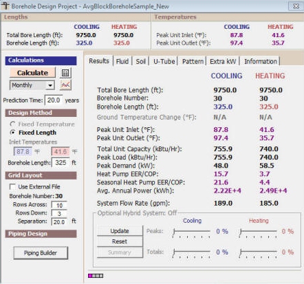
In the example below, the designer has determined the best design for the loopfield to be a 10x3 array of loops, 325 feet deep, with 20 feet separating each row and borehole.
The Piping System Builder has automatically recognized that there are 30 circuits in the loopfield.
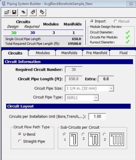
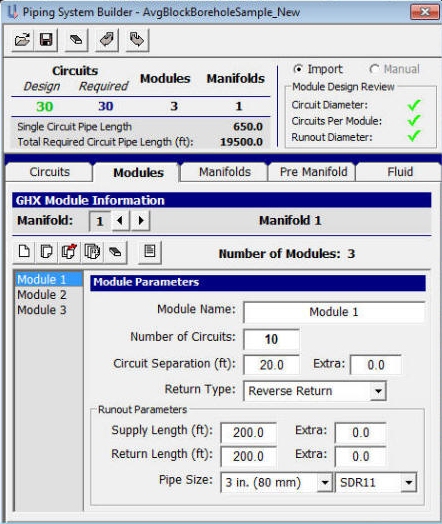
The user now has the opportunity to tell the Piping System Designer that the 30 boreholes will be configured as 3 groups of 10 boreholes. In this example, we will estimate that the circuits can be configured to to require supply return rounouts that are 200 feet from the equipment room and will use 3" pipe for the lines. Note that the Module Design Review shows three green checkmarks, indicating that the pipe sizes, circuits per module and runout pipe size are within acceptable ranges. A red "x" would indicate that the design needs to be checked in that area.
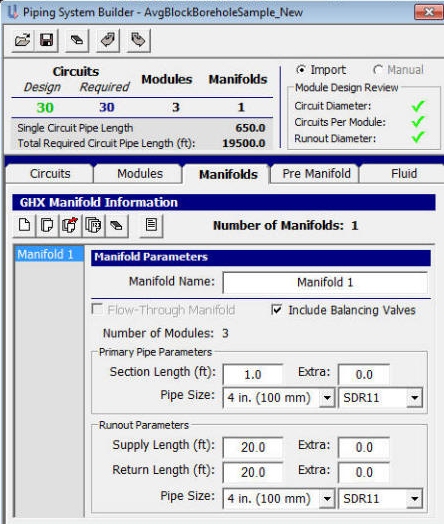
The Manifolds tabs allows the designer to describe the manifold that will be used and how far it is from the heat pumps as well as whether balancing valves will be used. In the real world, the runouts will all be different and balancing valves can compensate for the differences to provide a balanced flow through all of the circuits.
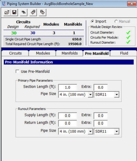
In some designs a "pre-manifold" may be used. In this example we will not use one.
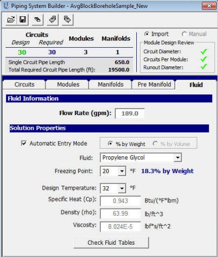
The designer now has the opportunity to tell the Piping System Designer what kind of fluid will be used in the loops. In this example, we will use a propolyne glycol solution that provides freeze protection to 20 degrees but the system will generally operate no lower than 32 degrees. This step allows the software to compute the effect of the extra viscosity that antifreeze will introduce to systems in colder climates. This impacts the pumping requirements to maintain proper turbulence in the circuits. The system will still be sized to use a water purge and the flow velocities for regular operation will take into account the additional viscosity of the antifreeze. Our flow rate came from the design simulation which was determined in the original loopfield design.
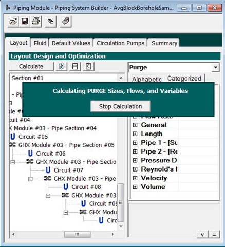
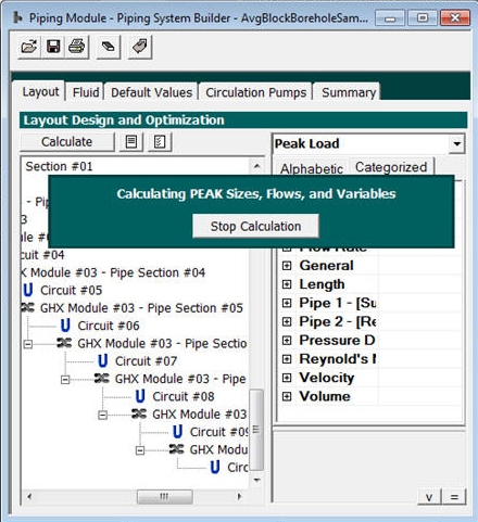
The Piping System Designer is now ready to compute the piping requirements. Here is what happens when the system is simulated: The system is sized with reducing connections to allow Purging that can be accomplished by realistic flows.
After purging sizes are computed, the system is simulated for Peak operating conditions:
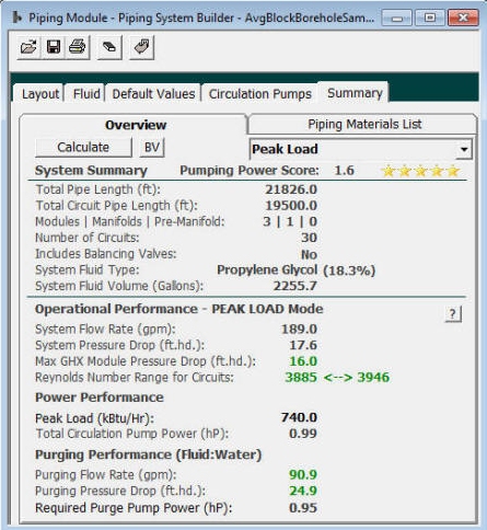
At the conclusion of the piping design, a summary is presented with an evaluation of the efficiency and Reynolds numbers achieved in the circuits:
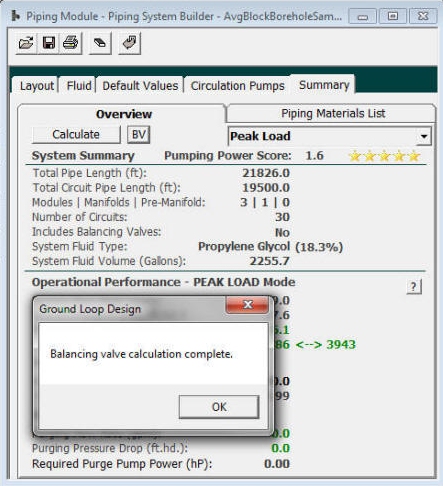
Since we specified balancing valves, the sast step is to apply the valves:
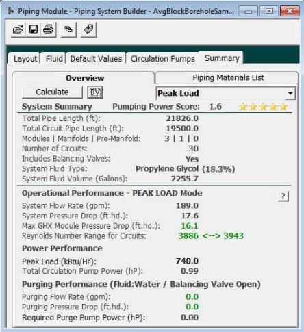
The final summary includes the balancing valves. Designers may now select the Peak, Purging or Equipment options to see the performance values for each condition.
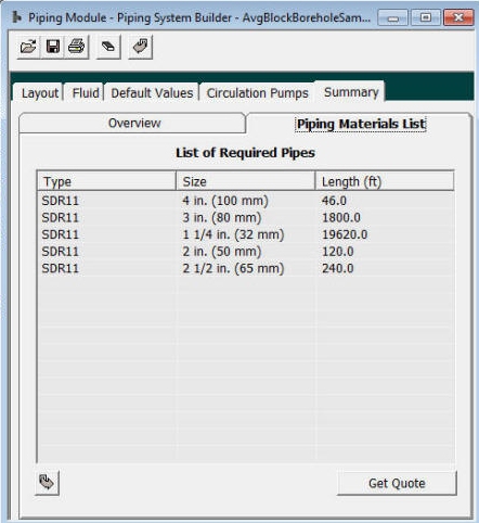
A new feature of the Piping Designer is the piping bill of materials. This is a feature that has been requested ever since the Piping Module was introduced with GLD2010.